Tuesday, April 30, 2013

Week 07: Progress

Construction Update: As per the builders advice on structure and design, the construction of the roof over the curtain wall is not supported by anything. There is an overhand of rafters, beams and roof structure which has no support. I have designed a column and beam structure for the Concrete model which will be constructed out of Steel I-Beams.


One Steel - Universal Beams
Hot Rolled Structural Steel sections produced by OneSteel are manufactured in accordance with the requirements of Australian/New Zealand Standard AS/NZS 3679.1 Structural steel.
AS Standard: AS/NZS 3679.1
Grade: 300PLUS, AS/NZS 3679.1-350
Size Range: 150 UB to 610 UB
Standard Length: 9.0m, 10.5m, 12.0m, 13.5m, 15.0m, 16.5m, 18.0m, 20.0m

-I have modelled in Revit Architecture the support structure and designed using a standard universal beam 200UB25
-The Steel universal beam standard lengths include 9.0, 10.5, 12.0, 13.5 and 15.0. These lengths will be adequate as our length of the structure is smaller than 9.0m.
-The Steel universal column I have modelled is a 200UC46.

http://www.onesteel.com/images/db_images/promotions/steel_in_housing_3rdednp1.pdf

Design


Image 01: Initial design in Revit with Universal Beams fixed to concrete slab

Image 02: Underside view of steel structure which will support the overhanging roof design.

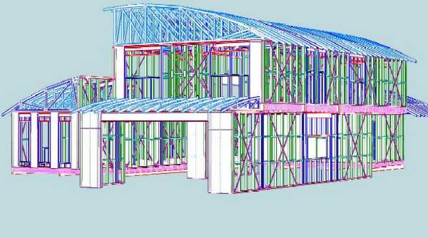
Image 03: An example of a 3D TImber frame model with Steel beams to support large openings


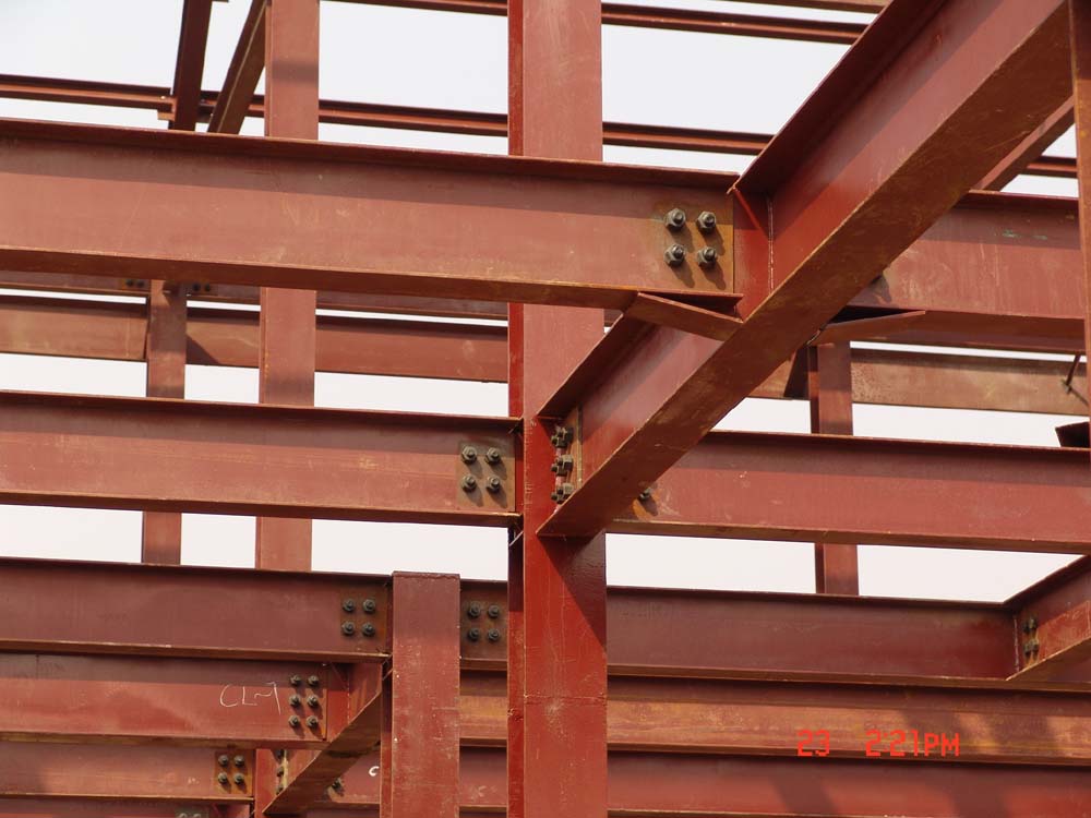
Image 04: Steel frame connection detail which includes being cut, welded and bolted. This image was a good example of the way the steel flanges and webs can be connected.


Image 05: Steel Stengths as per there shape. The I-Beams being the most supportive of large structures.

Image 06: Another example of a Timber frame building with a steel support structure over a large opening.


The connections between the steel beams and columns which they will be attached to the flange or web and connected by either being welded or bolted. 
-For our design we will weld the columns to the beams with no need for additional fixings or bolts.
01

02

03

References: 
http://yuanboit.en.made-in-china.com/productimage/TboxAqVMhwkn-2f0j00BZwagmbthQoU/China-Steel-Beam-Connection-for-Workshop.html

http://www.cadsoft-consult.com/blogs/architecture/2009/12/take-advantage-of-extensions-for-revit-structure-2010/

http://blog.lamidesign.com/2006/03/6030-house-floor-beam-day.html

http://housedamagephotos.blogspot.com.au/2011/03/steel-beam-header.html

http://forum.homeone.com.au/viewtopic.php?f=31&t=49878&start=10


Week 08: Intellectual Property Presentation

Presentations
There were two groups to present Intellectual Property Presentations this week. The presentations were extremely helpful for me as I am not familiar with IP and why it is important.

Interactive Architecture 

Clear Presentation using Prezi. Nice use of images to clearly explain the issues and processes involved with IP. There was a lot of information as well, a lot of background knowledge of IP in the industry. I have added some points i learnt from the presentation which i did not know before. There was also great use of referencing

Geriambiance

The presentation was clearly stating IP within their project. The written presentation was clear but the design was not completly engaging as it was used in PowerPoint.

IP

- It is a legal concept which refers to the creations of the mind for which exclusive rights are recognised. 
- The law gives the creator the exclusive rights
- IP can be bought, sold or licensed
-It distinguishes products or services from competitors.
- Prevents others from copying
- Most businesses have some form of IP that they need to protect

Types of IP


Patents

exp. 
-If you have developed a device, method or process which is new and useful, a patent can protect it.
-Does not include creations, models, plans, schemes
-It is legally enforceable and has exclusive rights
- 2 types of patents 
Standard (20 years)
Innovation (8 years)  
-72 month process

Trade marks

exp. Cadbury Chocolate - Purple
- protect name,logo. packaging, shape, colour, sound
- registered/un-registered
- 15 month process

Registered Designs 

exp. apple smart cover

-protect the appearance of a design
-Term 10 years
-needs to be need and distinctive
 
 Copyright
exp. Architectural drawings/ deisgn
-artistic, music, dramatic and literary works
-term life of author plus 70 years

Week 07: Communication Presentation

Communication presentation - Shades of Black

The simple prezi layout is effective with minimal text, large headings and interesting images. Communication is a major element of any project and needs to be organised accordingly.

The presentation was broken down into categories which included:

Methods - Strategies, Structure

Platforms

Responsibilities - Personal Roles

Integrity/Performance - measurements, project communication performance

Longevity - Relevance, Aims, Targeting Audience


There presentation gave a brief explanation to the sub-category in relation to the larger picture and then is referenced back to their project and how that has helped them through the stages of the assignment. This idea was the main concept in our presentation as well to breifly explain what we were talking about then linking back to the project we are working on.

Monday, April 15, 2013

Week 06: Planning Presentation


Aim of the Project
The aim of the project is a mixture of the reasons for undertaking the assignment as well as the opportunities that will evolve from it. The aims and objectives need to be analysed in the initial stages of the works to deliver a successful project. This planning section will develop the schematic design, ideas and collaborations to develop the project brief.

Our Project Outline
Project 'Situation Engine' is a visual expose, informative and communication tool that will enable clients, industry and trade professionals a perspective view in analysing stages of construction in a real time environment using CryEngine3. 
The project will produce two 3D models, recreated from the Revit Architecture Sample model that will comply with the Australian Standards and the National Construction Code. They will be showcased using the CryEngine3 program in real time displaying a live construction site. The project will emphasize different construction methods, various construction stages, different materials, tools and equipment that would likely be used on our assumed site in Sydney.
The overall result will allow clients to better understand and experience the stages within the engine, and allow trades professionals to manage construction phases, effectively reducing cost, time, and waste management. Additionally, it can be used as training environments for new or existing tradespeople entering the field.

Outputs
The outputs of a project need strategic planning and design outcomes to define the tasks and breakdown structure of the assignment. The ideas and implementation need to be clearly defined to complete the initial stages of planning any project. These outputs will determine project objectives, opportunities, risks and constraints. Once the outputs of a project are determined the collaboration of the team will establish project roles, structure, time frames and the individual and group milestones that need to be achieved.

Our Project Outputs
The project will engage the emerging technologies in an innovative way to inform people involved within the built environment.  The project will produce a real time construction site in a virtual environment placed in the CryEngine3. The initial planning of the assignment involved defining roles and structure of the team members.  

The establishment of the assignment was to create ‘a real life project’, to be built in the Eastern Suburbs of Sydney. The architectural planning based assessments include the  ‘assumed’ site, local planning and development controls combined with the recreated Revit Architecture sample models. Further research into the local authority and their planning instruments helped determine the design of the building and if they were to comply with the governing body. The construction of the models was researched and analysed using the Building codes and standards, feedback from Builders in Sydney and researching construction reports and precedents in the industry.  These stages have been completed and the next stages of the assignment have been planned and the roles and structure established.

The models designed through Building Information Modelling (BIM) will be placed into CryEngine3. The model will be separated into stages and construction details and methods displayed. The final interactive environment will explore how building designs can be displayed using the emerging technologies as an informative tool.


Sunday, April 14, 2013

Detailed Crysis Stages

Stage 01:

GROUND WORKS AND SUB-FLOOR


For Both models:
  1. First Site placed in Crysis (uncleared) - vegetation including trees, rocks, shrubs, existing slope and typography.
  2. Second Site placed in Crysis (cleared and excavated) - vegetation disappears  excavation of the site to the level of (underside of concrete slab), Site fences erected
  3. Third Site in Crysis (excavation) - excavation of strip and pad footings
  4. Prepare Footings for Concrete fill 
          - Construct form-work
          - Waterproof membrane (plastic sheeting)
          - Reinforcement Supports (Chairs)
          - Reinforcement (Bars and cages made up for strip and pad footings) 

    5. Place concrete into Crysis for the footings

Next...
01. Revit Sample Model:
  1. Preparation for Concrete slab on Ground
          - Construct form-work
          - Pipework for the dwelling (placed under kitchen, laundry and bathrooms) 
          - Vapour Barrier (Plastic sheeting)
          - Reinforcement Supports (Chairs)
          - Reinforcement (Bars and cages made up for strip and pad footings) 

02. Timber Model
  1. Fix Timber Post Anchors to Pad footings
  2. Fix Timber Posts
  3. Fix bearers to Timber Post grid, as per detail
  4. Fix Floor Joists

Tuesday, April 9, 2013

Site stages for Crysis

Acceptable Standards of Domestic Construction

1. Site Preparation

- Sediment control
ensure that sedimentation and erosion control measures are in place and maintained as required by the local authority. (Sediment fences, divert  uncontaminated water away from site, prevent contaminated water from leaving the site


http://www.yourhome.gov.au/technical/fs28.html

- Setup Site facilities
Contractors have to provide welfare facilities including Site toilets, access to water and allocated rest area as well as a site office, site materials storage, access routes, deliveries area, waste management, appropriate signage and fencing as needed

- Clearing the site
Clear vegetation and organic matter from the area of the building, clear approved trees to be removed, tree roots and stumps from 2 metres around the extent of the building. Retain topsoil for later use. Protect existing trees by fencing them off  to prevent filling or excavation of the root system. 

2. Sub Floor Structure

- Foundations
The footing designs are to comply with the Australian Standard AS2870 and to be certified by a structural engineer.

- Excavation and Filling
Excavate trenches for footings to an even-bearing capacity.

- Site Drainage
Provide subsoil drains to the higher side of excavation in sloping site excavtions. Build drains with falls to storm-water lines to a min of 1:100 fall.

-General
    - Order Steel Reinforcements, waterproof membrane, reinforcement supports, sand and        fill for appropriate  footing design.
    - Construct Steel Reinforcement 'cages' on site and place into footings
    -  Fill with Concrete


Wednesday, April 3, 2013

Week 05: Progress

1. Timber bearer detail

Timber Post-Beam Connection

This detail I have been researching for a few days looking at construction details, standards and specifications.  I have been trying to figure out the detail which will support the timber bearer to the timber post either notching, bolting or fixing. There are numerous ways to connect the elements but the metal brackets are most commonly used connectors in the construction industry.


AS 1684.2 Residential timber-framed construction


PART 9.2 General Connection Requirements


9.4 Nominal and specific fixing requirements

To determine nominal and specification connections the wind speed needs to be determined. As our site is situated in Sydney, Australia. The geographical region is Region A, non cyclonic.


The site terrain category is classified as open terrain including sea coast areas, airfields, grassed with few

well scattered obstructions, such as isolated trees and uncut grass, having heights from 1.5m to 10m. The topography classifcation falls under T3, situated high on the cliffs of the Dover heights.

Wind Classification: N3


 Table 9.2

Connection:
Lower storey floor frame to supports requires - nominal (minimum) connection only.

Table 9.4

Minimum fixing for each joint:
Floor framing - Bearer to timber stump/post
4/75 x 3.33 mm or 5/75 x 3.05 mm machine driven nails plus 1/30 x 0.8 mm G.I. strap over bearer and fixed both ends to stump with 4/2.8 mm dia. each end;
OR
1/m10 bolt through bearer halved to stump;
OR
1/M12 cranked bolt fixed vertically through bearer and bolted to stump plus 4/75 x 3.33 mm or 5/75 x 3.05 mm machine-driven nails

-The connection we will use in the project will be the T-Strap which bolts and nails the strap to both the timber post and timber bearer at each joint. The fixing will comply to the nominal requirement for fixing the sub floor frame.


http://homeservices-directory.com/homeowners/tips/beam.html

http://blog.siffordsojournal.com/2011/12/house-update-xi-porch-cross-beams.html
http://www.familyhandyman.com/DIY-Projects/How-A-House-Works/How-The-Structure-Works/how-to-repair-a-load-bearing-post/View-All

2. Bearers

Hyspan timber framing is a structural range of timber elements that are widely used in Australia. To determine bearer sizes and spans the RLW (Roof load width) and FLW (Floor load width) need to be calculated from AS1684.


Floor Load Width

Bearer A
(17.4m)
= X + Y/2
= 0 + 3/2
=1.5

Bearer B
(17.4m)
=Y + Z/2
=3 + 3/2
=3

Bearer C
(17.4m)
=z/2
=3/2
=1.5

Roof load Width

Wall A
RLW = X/2 + a
          = 16/2 + 0.6
          = 8.6

Bearer A-  Hyspan (supporting upper storey load bearing walls) 300d x 75b
                   3.9 Maximum Single Span
Bearer B- Hyspan (supporting floor loads only) 300d x 75b
                  5.3 Maximum Single Span
Bearer C- Hyspan (supporting upper storey load bearing walls) 300d x 75b
                 3.9 Maximum Single Span


Sketches showing the grid of the posts, Bearer A + C are the same dimensions and are supporting upper loads with 6 posts and footings. Bearer B is supporting floor loads only with 5 posts and footings. All bearers are the same dimensions 300 x 75 Hyspan

More fixings for Post Beam connections


http://www.diyadvice.com/diy/decks/build/install-beams/
http://tamlyn.com/PostBeamCaps.html
http://www.homehardware.ca/en/rec/index.htm/Hardware/Lumber-Connectors/Dimensional/Caps-Bases/4-x-4-18-Gauge-G185-Post-Beam-Cap/_/N-ntjwe/R-I2682250
http://www.finehomebuilding.com/how-to/articles/top-10-deck-building-mistakes.aspx

3. Floor Joists

   - Hyspan 240 mm x 45 mm
   - 450 Spacing (centres)
   - 6.1 maximum continuous span   - allowed overhang 1.5 m


On site image displaying Hyspan Timber Bearers and Timber floor joists connected to timber posts.

Floor joists are the next series of members for the sub-floor frame. They are supported by the bearers.
Typically the floor joists run over the tops of bearers, however, they may be attached to the sides of bearers. Like bearers, floor joists may be single span or continuous span.


http://toolboxes.flexiblelearning.net.au/demosites/series10/10_01/content/bcgbc4010a/10_floor_systems/10_sub_floor_framing_floor_joists/page_001.htm


4 Timber Frame construction to skillion roof

I have been researching the Residential Timber frame construction standards to calculate a design that will comply with codes and standards.


-model formwork

Tuesday, April 2, 2013

Week 04: Progress


Russell's Feedback:
Instead of two buildings to compare building construction types which we previously decided to go ahead with we will now change:
    - The remodel of the Sample Project to Australian building standard types (exp. Precast concrete changed to reinforced block retaining walls and brick veneer.
    - To create another model constructed out of Double brick with piers with cut and fill.

We will now keep the Sample Project entirely constructed as is only checked to Australian Standards and the Building Code.

We will now create another building constructed out of timber frame construction to show the client the cheaper alternative? more sustainable? lighter structure? more time efficient? - These options can be discussed with the builder/ client once the BIM to CryEngine resource is provided.

Objective
To make our project as if it was a 'real life' project, to be planned, designed and constructed in the Eastern Suburbs of Sydney. We have now assumed data for our site to collect information, standards and legislation to follow when we are designing our buildings for construction. 
Assume:
Location- Dover Road, Dover Heights
Site Classification- Class A, Sand and Rock
Council- Waverley Council
Legislation-  Development Control Plan and Development Control Plan

Quick view through the legislation:
Mapping - R2 Low Density Residential
Building Height Max - 8.5m
Heritage - Not Applicable
Floor Space Ration - 50:1
Side setbacks - 900mm
Rear building line - rear line of neighbouring buildings
Fences - 1200mm high (max)

Aim
To design and plan following the state and local legislation

Image01: Our chosen site in Dover Heights
maps.google.com.au

New Work:
Model 01:

-Original Model
-Check NCC and Aus Standards

Previous research work that can be included:
-Pad footings for steel structure (1000x1000x500mm) min 500 below ground level
-New Drywall on basement walls ( Timber stud)
- Check specifications for timber sizes (Hyspan on Dropbox, Acceptable standards of domestic construction)
- Concrete reinforcing ( Acceptable standards of Domestic Construction lists the trench mesh sizes as well as the reinforcement bars, lapping, there needs to be cover for the concrete (min. 50mm)
- Spans for construction ( Acceptable standards of Domestic Construction)

Need to model:
-Reinforcing Supports (Chairs)
-Formwork + bracing

Model 02:

-New model
-Timber frame construction (Floor, walls etc.)

Include:
-Brick piers
-Ant-caps
-Cladding - Blueboard or Weatherboard

Research
-Spans
-Load-Bearing
-Timber specifcation sizes for Australia