Friday, March 22, 2013

Builders Meeting + Construction Information

After numerous meetings with builders and people in the construction industry. I was given feedback about our design in Revit and there were a few queries that I had to research. I was also given feedback on the way this building would be built and the construction stages that would be used in the industry today in Sydney, Australia.  I printed plans, elevation and sections of the design to take to this meetings and wrote notes.

The feedback included:
- There needs to be a steel structure supporting the roof
-There needs to be pad footings for the existing steel columns and beams as they are sitting on the ground. ( 1000x1000x500mm 500mm below ground level
- The concrete slab on the ground floor needs to be extended under the fireplace
-Strip drain for the house retaining walls, with Blue metal back fill
- 30 degree batter from the top of the footing
-Waterproof member needs to be placed on all walls under ground level
-Research Nylex Strip Drain
-Dry Wall for the interior walls as moisture is going to be a major issue.
-Adjust strip footings, at the moment there is a strip footing then peirs then an edge beam and slab- This design is pointless
-Hyspan, look at the span tables as this product is mostly used in the construction industry
The minutes..


BIM Modelling-

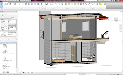
Image01: I have remodelled the sample model sub floor to suit the standard retaining/ footing detail (image02) The blockwork walls will be tied in with concrete footings and slabs.

Image02: a typical retaining wall detail where our site has a 2000mm height making our strip footing 1400x650x450 with standard N20-400.


Image03: This is a long section cut through the building showing the new designed slab floor


Image04: A cross section, walls need to be adjusted so the concrete block walls start flush with the strip footings.


Image05: The blockwork modified up to level 2, windows need to be adjusted.


Image06: need to model pad footings for the steel support structure.


Image07: Windows are placed and adjusted as they were within the ground line.


Image08:I have modelled the pad footings for the support stuctures which include 1000x1000x500mm. As steel and timber structural posts cannot be placed into the ground without foundations.


Image09: another view


Image10: section cut showing the new strip and pad footings.

Image11: A construction detail I drew a few years back. This detail can be used to help model the timber skillion roof which meets a brick veneer construction.


Image12: I have modelled in a Dry wall (timber frame) with a 50mm cavity of the blockwork walls. This will pretect the interior of mould and moisture as the blockwall is retaining soil, moisture is likely to be present.


Image13: I have lined up the ground floor timber walls with the first floor timber walls. The cavity air gap for this level is 140mm. Need help to determine construction detail, need wall ties and a waterproofing strategy for the timber frame.

Image14: i have modelled the connection where the concrete block walls meet the brick veneer.

Image15: Connection issue with the timber frame floor and wall (there needs to be a flashing for moisture) The timber floor construction could line up with the wall construction (but again waterproofing in the cavity needs to be considered. Timber frame is easily damages if exposed to water


Week 03: BIM to CryEngine

To Do List:
-Present Back Brief
-Extensive Construction research
-Research and develop final construction stages and phases
-Arrange Builders meeting
-upload dropbox files (including BCA, standards and construction information.


Draft Construction and work stages breakdown

For our project, we will be modelling and showcasing two different construction types including Brick Veneer and Timber Frame construction. As these two construction methods are relevant to Sydney and are most frequently used.


Basic Construction Stages:

Base Stage (sub-floor, foundations, concrete, under-slab plumbing, initial electrical, site survey and building setout etc)
Frame Stage (frames (walls), trusses are erected – roof is sometimes installed along with guttering and fascia)
Lockup Stage (pre-wire electrical completed, plumbing rough-in completed. External walls completed with all external doors fitted.
Pre-Paint Stage (internal walls and doors are completed, plastering finished, and the house ready to be painted.)
Completion (finishings including kitchens, tiling, electrical, plumbing fit-off, floor coverings etc)

Brick Veneer Construction

- The brick facade is anchored to the timber frame of the house with metal brick ties. 
- The brick veneer does not support the roof loads as all structural loads are supported by the timber frame. The Brick wall acts as a cladding. 
- There is a 50 mm cavity space between the timber frame and the brick walls. This air gap helps stop water from damaging the timber frame and the internal linings.

Three main stages.

Stage one:
This stage is the footings or slab for the floor. The ground and site are prepared and the drainage pipe laid in place. Then the concrete slab is laid down over and around the pipe and waterproof barrier. If the house was to be a timber floor the footing would be laid and then the brick work laid to floor height. Then the timber floor constructed.
Stage two:
The next stage is to construct the main timber frame complete to the roof. The eaves, windows and electrical box installed. The interior linings are not fixed until the roof is covered, and internal plumbing and electrical are completed.
Stage three:
The brick veneer can now go ahead and be laid right up to the eves and roof. As the brick work is laid a damp course and weep holes will be added. As the brick work is laid it is essential that the gap between the timber frame and the brick wall is kept clean. Also the weep holes must be kept clean and open. If it rains during construction the water will run down the walls and out of the weep holes until the roof is complete. As the brick veneer is constructed the brick layer will attach metal brick ties to the timber frame at set intervals. These brick ties help keep the brick veneer braced to the timber structural frame.
Problems and tips
One of the main problems to brick veneer is ground movement. Often the footings are not constructed well enough to cope with the movement of the ground. This is seen more and more in times of drought or high rain fall where the ground expands and contracts more than normal. Also because of cost and bad building practice not enough brick ties are put in and if cracks form the wall can become unstable.
Tips:
For new construction have your brick layer insert filters into the weep holes to exclude pests and vermin.
Make sure all garden beds allow for an air gap between the brick walls and the garden bed. This stops excessive moisture comings into your home and help stop mould forming in your walls.
concrete pad footings for the structural steel beams and columns. As well as the dry wall 50mm off the concrete block wall.

BIM modelling

Upon research on construction methods I have started modelling with Revit Architecture and modifying the Revit Sample Project to be Brick-Veneer construction.

Image01: I have redesigned the strip footings according to The Acceptable standards of domestic construction.

Image02: After initial meeting with the builders, they gave me feedback for the foundations. To have a concrete strip footing, Block retaining wall, thickened edge beam and concrete slab. I have modelled the footings according to
Image 03: The natural ground level is sloped down the site. This is an issue as the walls on the ground floor are retaining soil. As the sample model is constructed out of solid concrete with a timber cladding that is beneath the ground line this will need to be adjusted.

Image04: As a standard from of retaining construction used in Sydney is Reinforced concrete block walls. I have chosen to use this construction and take the level of the retaining walls up to level 2. This will make the connection details easier to construct.

Image 05: In this image I have adjusted all internal stud walls to stop under the floor construction. In the sample model the walls were constructed up to the timber floorboards. As I have had much discussion about the purpose of the strip footing in which the site will need to be over excavated to actually construct this as well as the foundation wall acting as a continuous pier, where instead a slab on ground and footing sub-floor would be more realistic. 

Image 06: The walls have been constructed out of reinforced concrete blockwork up to level 2 for retaining and waterproofing issues. The blockwall starts at the Ground floor slab level.

Image07: The Concrete walls completed without the existing windows, these need to adjusted as two were obstructed by the natural ground line (NGL). 

Image08: All internal stud walls are adjusted to suit.

Week 02: Groups

Group Wiki


https://sites.google.com/site/3rdiconstruct/

Nikko: Project Manager, all jobs overview
Salli: Construction, NCC, Revit, Modelling, Presentation
Daniel: Crysis, Animation, Media, Modelling
Tim: Crysis, Animation, Modelling
Matt: Media, Modelling, Rendering
Deme: Presentation, Mdeia, BCA, Construction